Skip to content

Gas analysis system “GAS” 

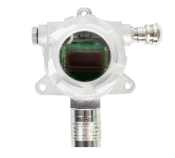
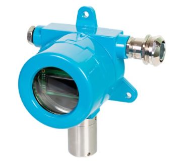
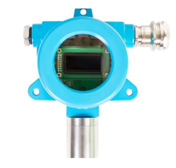
The sensor includes a replaceable gas sensor for propane or methane, a special stainless steel housing with a stainless filter to protect the sensor, and a built-in spark barrier to ensure explosion protection requirements for the gas sensor. 
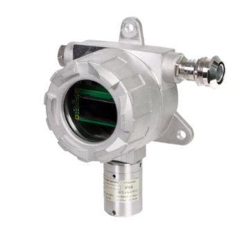
The high level of explosion protection of the gas analyzer sensor is ensured by well-thought-out design solutions

Limiting the power supply voltage to the gas sensor to 5.4V

Using spark-proof barriers consisting of three Schottky diodes connected in series, three 1SMB5918V zener diodes connected in parallel, and current-limiting resistors with a total resistance of 25 ohms and a total power of 3 watts

Current and voltage limits in the UART digital interface circuits (TX and RX circuits)

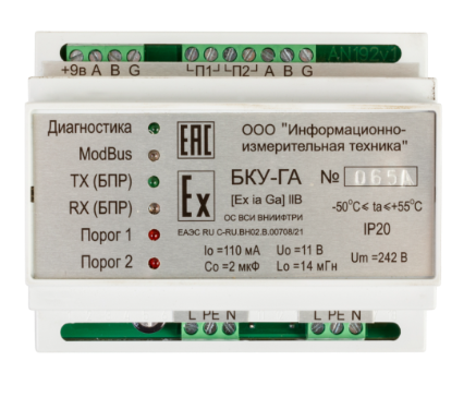
It is used to connect BPR-GA and DGA with a voltage of up to 5.4 V using spark-proof barriers consisting of three 1SMB5918 V voltage stabilizers connected in parallel and 510 Ω 1 W current-limiting resistors.

Compounding with epoxy glue VK-9 (according to TU 1-595-14-842-2004, OST V 84-2081-83)

Elements that provide the required level of explosion protection for DGA, see ATUSH.413311.001 SB

manufacturing a special-designed stainless steel DGA housing, including a filter

On one side, the housing has an external thread; on the other side, there is a hole covered with a steel mesh. Inside the housing, there is an optical gas sensor and a spark protection barrier. Wires extend from the DGA sensor to connect it to the BPR-GA unit.

The sensors and units comply with the requirements of TR CU 012/2011,
GOST 1EC 60079-14-2013

They are designed for use in hazardous areas and comply with the requirements of the Regulations on the Use of Electrical Equipment in Explosive Gas Environments, as well as the ATUSH.400000.001 RE user manual.

The main transmission within the system is carried out via the RS485 interface lines

In addition, the BKU supports TCP/IP protocol and data transmission over a standard Ethernet line for communication with the operator's workstation.

The connection is made via an RJ45 connector. The system's communication line parameters are listed in the table below.
Мы используем файлы Cookie для улучшения работы, персонализации и повышения удобства пользования нашим сайтом. Продолжая посещать сайт, вы соглашаетесь на использование нами файлов Cookie.